Between the inverters (typically 400–800 V) and the grid (11, 22 or 33 kV and above) sits the step-up transformer. Undersize it and it overheats or limits export; oversize it and the project pays for copper, iron and no-load losses it never needed. Solar transformers also see unusual duty: daily full-load cycles, inverter harmonics and, often, very high ambient temperatures.
Quick answer: size the transformer on apparent power (kVA), not kW: at least the active power to be exported divided by the required power factor, and normally at least the total kVA the connected inverters can inject, corrected for the site's ambient temperature. For a 2.5 MW plant that must operate at pf 0.95, the minimum is 2,500 / 0.95 = 2,632 kVA; with eight 320 kW / 352 kVA inverters (2,816 kVA), a 3.15 MVA standard unit — or a custom rating of about 2.8 MVA — is the usual choice.
Introduction
Beginner understanding: Inverters produce electricity at low voltage. To send it over the grid efficiently, a transformer raises the voltage. The transformer must be big enough to carry all the power the inverters can produce, including a part called reactive power, even on the hottest day.
Engineering understanding: Transformer capability is thermally limited by current, i.e. by apparent power S = √(P² + Q²). The rating must cover the maximum simultaneous inverter output (or the plant controller's export limit) at the required power factor, at the site's ambient conditions (IEC 60076-2 temperature-rise limits assume normal service conditions, including a maximum ambient of 40 °C; hotter sites need derating or a design for higher ambient). Impedance sets fault levels and voltage regulation; losses (no-load and load) affect lifetime energy; the vector group and neutral earthing must suit the inverter manufacturer's requirements and the grid.
What is it?
| Parameter | What it means | Why it matters |
|---|---|---|
| Rated power (kVA/MVA) | Continuous apparent power at rated conditions | Must cover inverter kVA |
| Voltage ratio | e.g. 33 kV / 0.8 kV | Matches grid and inverter AC voltage |
| Impedance (%Z) | Voltage drop at rated current with the LV shorted | Sets fault current and regulation |
| No-load loss (P0) | Core loss, present whenever energised | Paid 24 h a day |
| Load loss (Pk) | Copper loss at rated current | Scales with load² |
| Vector group | Winding connections and phase shift | Earthing, inverter compatibility, parallel operation |
| Cooling | ONAN, ONAF, dry-type AN/AF | Rating, footprint, maintenance |
Why is it important?
- It is a single point of failure for the whole inverter block.
- Undersizing causes overheating, accelerated insulation ageing or export limitation.
- Oversizing raises capital cost and no-load losses (which occur even at night).
- Impedance determines the LV fault level that switchgear and cables must withstand (see cable sizing and short-circuit withstand).
When is it used?
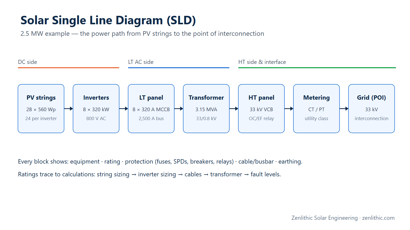
During electrical concept design (block sizing), in the DBR and SLD, in the transformer technical specification for procurement, and in the energy model (transformer losses in the PVsyst loss chain).
Where is it used?
C&I plants connecting at 11 kV, utility plants with inverter-duty transformers in each block (e.g. 0.8/33 kV), and pooling substations stepping 33 kV up to 66–400 kV.
How does it work?
Required S ≥ P_export / pf_required
Inverter S_total = N_inv × S_inv,max
Rated current I = S / (√3 × V_LL)
Through-fault current (infinite source) I_f ≈ I_rated / (%Z / 100)
Annual loss energy ≈ P0 × 8,760 h + Pk × Σ (S/S_rated)² × Δt
Required Input Data
| Input | Example |
|---|---|
| Export capacity and power-factor requirement | 2.5 MW at pf 0.95 (grid requirement — confirm in connection agreement) |
| Inverters: number, kW, max kVA, AC voltage | 8 × 320 kW, 352 kVA max (assumed datasheet), 800 V |
| Grid voltage | 33 kV |
| Site maximum ambient temperature | From site data / specification |
| Transformer losses (P0, Pk) | Manufacturer's guaranteed values |
| Load profile | Hourly output (PVsyst) for loss energy |
Step-by-Step Design Process
- Fix export capacity, pf range and grid voltage.
- Sum the connected inverters' maximum apparent power.
- Required rating ≥ max(P/pf, inverter kVA unless export is limited by a plant controller).
- Apply ambient/altitude correction for site conditions per the specification.
- Select a standard or custom rating; set the voltage ratio and tapping range.
- Choose impedance; calculate LV and HV fault currents.
- Choose vector group and neutral earthing with the inverter OEM and utility.
- Specify losses (P0, Pk) and include them in the energy model.
- Specify protection (see below) and record everything in the DBR and SLD.
Formula
S_req = P / pf
I_HV = S / (√3 × V_HV)      I_LV = S / (√3 × V_LV)
I_f,LV ≈ I_LV / z            z = %Z / 100 (source impedance neglected → upper bound)
E_loss ≈ P0 × 8,760 + Pk × h_eq       h_eq = equivalent full-load loss hours from the hourly profile
Numerical Example
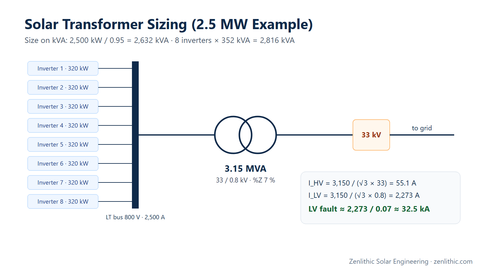
A 2.5 MW (AC export) plant with eight 320 kW string inverters (352 kVA maximum apparent power each — assumed datasheet value), 800 V AC, connecting at 33 kV, required to operate at pf 0.95 at full output.
Engineering Calculation
Step 1 — Apparent power required
By export requirement: S = 2,500 / 0.95 = 2,631.6 kVA
By inverter capability: 8 × 352 = 2,816 kVA
Step 2 — Rating selection
The transformer should carry the inverters' maximum apparent power unless the plant controller limits injection. Options:
- 3.15 MVA (a standard preferred rating above 2.5 MVA) — margin for ambient derating;
- a custom ≈ 2.8 MVA inverter-duty unit matched to 2,816 kVA — common for large repeated blocks, subject to the specification's ambient requirement.
Step 3 — Rated currents (3.15 MVA, 33/0.8 kV)
I_HV = 3,150 / (√3 × 33)  = 55.1 A
I_LV = 3,150 / (√3 × 0.8) = 2,273 A
Step 4 — Impedance and fault level
IEC 60076-5 lists recognised minimum short-circuit impedances by rating (for example 6.0 % up to 2,500 kVA and 7.0 % for 2,501–6,300 kVA — confirm against the edition in your specification). With %Z = 7 %:
I_f,LV ≈ 2,273 / 0.07 ≈ 32.5 kA   (upper bound, infinite grid)
I_f,HV (through-fault, HV side) ≈ 55.1 / 0.07 ≈ 787 A
The LV switchgear and busbar must be rated for the LV fault level (plus the inverters' own fault contribution, which is limited and given by the OEM).
Step 5 — Loss energy (illustrative; use guaranteed losses and the hourly profile)
Assume P0 = 2.8 kW, Pk = 25 kW and h_eq = 1,300 equivalent full-load loss hours per year:
No-load:  2.8 × 8,760 = 24,528 kWh/yr
Load:     25 × 1,300  = 32,500 kWh/yr
Total                 ≈ 57,028 kWh/yr  ≈ 1.14 % of 5.0 GWh annual output
No-load loss runs all night, which is why low-loss cores and correct sizing matter for solar.
Practical Solar Application
- The transformer rating defines the block size: one 3.15 MVA transformer per eight 320 kW inverters in this example.
- The LV fault level drives the LV panel/ACB rating and cable short-circuit checks in the single line diagram.
- Guaranteed losses go into PVsyst's transformer loss settings, feeding PR (see PR, CUF and generation).
Design Considerations
- Ambient temperature: hot sites often need designs for a higher ambient than IEC's normal service conditions — follow the project specification.
- Harmonics: inverter-duty transformers should be specified for the inverter's harmonic spectrum.
- Vector group and earthing: set with the inverter OEM (many string inverters require a specific LV earthing arrangement) and the utility; common arrangements include Dy11-type units for inverter-duty service — confirm for your equipment.
- Protection: at minimum HV overcurrent and earth-fault protection (VCB/RMU with relay), plus transformer-mounted devices for oil units (e.g. Buchholz relay, oil and winding temperature indicators, pressure relief) as per the specification.
- Oil vs dry-type: oil-filled (ONAN) units dominate outdoor utility blocks; dry-type suits indoor/rooftop C&I installations.
- Efficiency standards: distribution-transformer efficiency levels (e.g. BIS/BEE in India) may apply depending on rating and scheme.
Common Mistakes
- Sizing in kW and ignoring reactive power.
- Ignoring ambient derating on hot sites.
- Ignoring the inverters' maximum kVA (which can exceed their kW rating).
- Specifying impedance without checking LV fault level against switchgear ratings.
- Forgetting no-load loss runs 24 h a day.
- Choosing a vector group without the inverter OEM's earthing requirements.
Key Notes
- Size on kVA: S ≥ P / pf and ≥ connected inverter kVA (unless export-limited).
- I = S / (√3 V); I_f,LV ≈ I_LV / z.
- IEC 60076-5 gives minimum impedances by rating; the specification may set its own.
- Transformer losses are typically around 1 % of energy — include them in PR.
Engineer's Checklist
- Export MW, pf range and grid voltage confirmed
- Inverter maximum kVA summed
- Rating selected with ambient/altitude correction
- Voltage ratio and tap range specified
- Impedance chosen; LV/HV fault levels calculated
- Vector group and neutral earthing agreed with inverter OEM and utility
- Guaranteed P0 and Pk in the spec and in PVsyst
- Protection devices specified
- Rating consistent across DBR, SLD and BOQ
FAQ
How do I calculate transformer size for a solar plant?
Divide the export active power by the required power factor to get kVA, compare with the total maximum kVA of the connected inverters, take the larger (unless a plant controller limits export), and correct for site ambient temperature before choosing a rating.
What size transformer is needed for a 2.5 MW solar plant?
At pf 0.95 the minimum is about 2,632 kVA; with eight 320 kW / 352 kVA inverters (2,816 kVA), a 3.15 MVA standard or ≈ 2.8 MVA custom inverter-duty transformer is typical, subject to ambient derating.
Why is transformer impedance important?
It limits fault current and affects voltage regulation. A lower impedance means a higher LV fault level, so switchgear and cables must be rated for it.
Should a solar transformer be oil-filled or dry-type?
Outdoor utility and ground-mounted blocks commonly use oil-filled (ONAN) units; indoor or rooftop C&I installations often use dry-type for fire safety. The specification and site decide.
How much energy do transformer losses cost?
Typically around 1 % of annual energy, split between no-load (constant) and load losses (proportional to the square of loading). Use the manufacturer's guaranteed losses and the hourly profile to calculate it.
Conclusion
Size solar transformers on apparent power at site conditions. In the example, 2.5 MW at pf 0.95 needs at least 2,632 kVA, eight 352 kVA inverters can inject 2,816 kVA, and a 3.15 MVA unit (55.1 A HV, 2,273 A LV, ≈ 32.5 kA LV fault level at 7 % impedance) is a sound selection — with losses carried into the energy model.
Related reading: How to prepare a solar SLD · DC/AC ratio and inverter sizing · kW vs kWp vs MW vs MWp
Need professional solar PV design, PVsyst simulation, AutoCAD drawings or electrical design support? Zenlithic provides solar design consultancy and engineering support for rooftop, C&I and utility-scale projects — transformer sizing, HT/LT design, SLDs and DBR documentation. Explore Zenlithic Solar or contact our engineering team.