Most PV plants today are built with more DC module capacity than AC inverter capacity. A 10 MW (AC) plant might carry 12–14 MWp of modules. This "overloading" is deliberate: modules rarely produce their nameplate power in the field, so a larger DC array keeps the inverter working near full load for more hours of the day. The cost is clipping — on the sunniest hours the inverter limits output and some energy is lost.
This guide explains how engineers size inverters and choose the DC/AC ratio, and shows how to calculate the irradiance at which clipping begins.
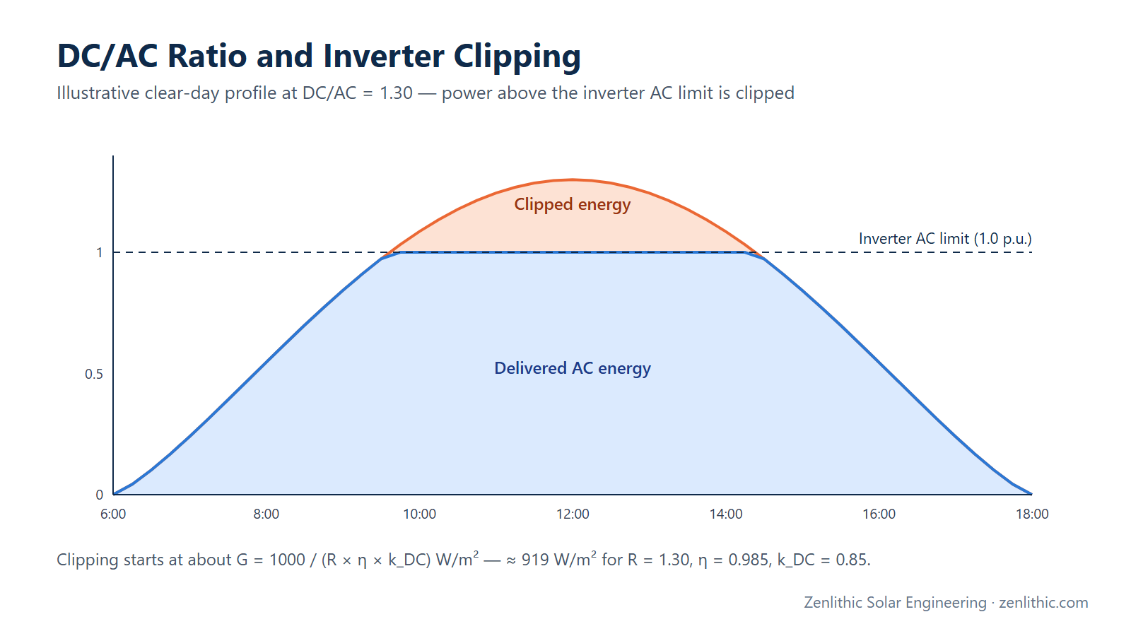
Quick answer: DC/AC ratio = DC kWp ÷ inverter AC kW. Size the inverters from the grid export capacity (with kVA headroom if reactive power is required), then add DC capacity up to the ratio an hourly simulation shows is economic — often 1.2–1.45 for Indian utility plants — without exceeding the inverter's input limits. Clipping begins at roughly G = 1000 / (R × η × k_DC) W/m², about 919 W/m² at a ratio of 1.30.
Introduction
Beginner understanding: The DC/AC ratio compares the size of the solar panels (DC, in kWp) with the size of the inverter (AC, in kW). A ratio of 1.3 means 1.3 kWp of panels for every 1 kW of inverter. Panels usually produce less than their label value because of heat, dust and losses, so a slightly larger panel array lets the inverter produce more energy over the year. If the array is too large, the inverter cuts off the extra power on very sunny hours; this is called clipping.
Engineering understanding: Inverter sizing is an optimisation between inverter capital cost, energy yield (clipping loss increases with ratio), grid-connection limits, reactive-power requirements and the inverter's DC input hardware limits (MPPT count, inputs per MPPT, maximum input current and maximum DC power). The optimum ratio is site-specific, depends on the irradiance distribution and temperature, and is normally confirmed with an hourly simulation such as PVsyst.
What is it?
DC/AC ratio (also called inverter loading ratio, ILR):
DC/AC ratio = Total DC capacity at STC (kWp) / Total inverter AC rating (kW)
Inverter sizing is the selection of inverter type (string or central), unit rating, quantity and the number of strings connected to each inverter and MPPT.
| Term | Unit | Meaning |
|---|---|---|
| kWp / MWp | DC | Module nameplate power at STC |
| kW / MW (AC) | AC | Inverter (or plant) active power rating |
| kVA / MVA | AC | Inverter apparent power rating (active + reactive) |
| Clipping | — | Inverter limiting output at its AC (or current) limit |
Why is it important?
- Energy per rupee/dollar invested: inverters and AC balance-of-system are sized on AC; adding DC capacity raises energy at a lower marginal cost.
- Grid-connection limit: the export capacity is fixed by the connection agreement (for example a 10 MW connection). Energy is maximised within that limit by a higher DC/AC ratio.
- Hardware limits: inverters specify maximum DC input power, MPPT current and number of inputs — these can cap the ratio before economics do.
- Losses: too high a ratio produces excessive clipping; too low leaves the inverter under-utilised for most of the day.
When is it used?
- At concept stage, to fix plant DC and AC capacity for the bid or feasibility study.
- In detailed design, to fix inverter quantity and strings per inverter after string sizing.
- In PVsyst, where the "inverter sizing" and "overload loss" results confirm the choice.
Where is it used?
All grid-connected systems. Utility-scale plants typically use higher ratios; rooftop and C&I plants are often limited by roof area, net-metering rules or sanctioned load, which can cap the DC capacity. Typical industry ranges (for example 1.2–1.45 for many utility plants in sunny regions) are practice, not a standard — the right value comes from simulation and project economics.
How does it work?
The DC array's actual output is well below its STC rating most of the time because of:
- irradiance below 1000 W/m² for most hours,
- cell temperatures above 25 °C (a temperature loss of several percent on hot days),
- soiling, mismatch, DC cable losses and module degradation.
When the DC power available at the inverter input, multiplied by the inverter efficiency, exceeds the inverter's AC limit, the inverter moves its operating point away from the maximum power point (raising the DC voltage) to hold output at the limit. That excess is the clipped energy.
Required Input Data
| Input | Source | Example |
|---|---|---|
| Contracted AC export capacity | Connection agreement / PPA | 10 MW at point of interconnection |
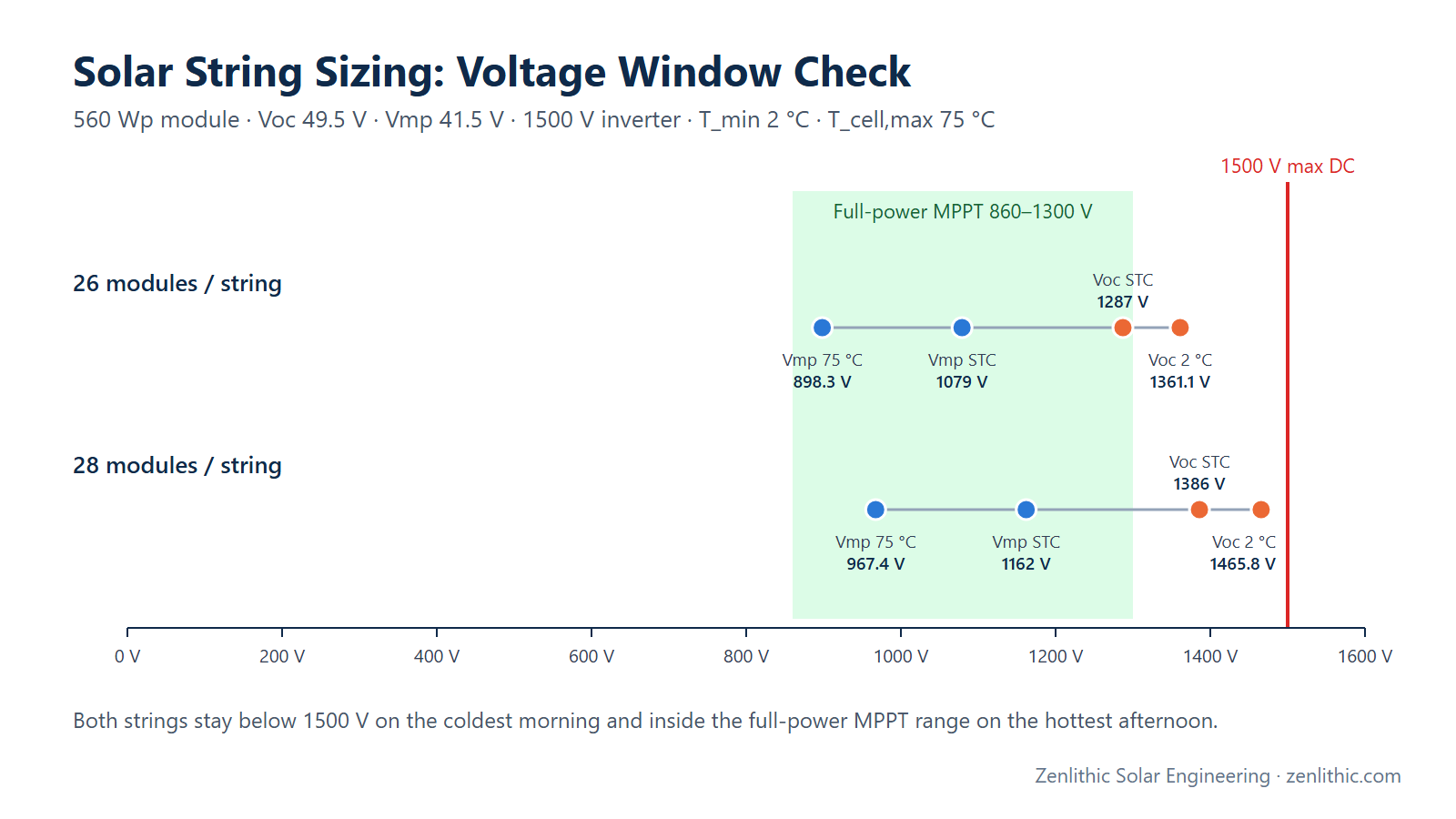
| String configuration | String sizing | 28 × 560 Wp = 15.68 kWp per string |
| Inverter AC rating (kW / kVA) | Inverter datasheet | 320 kW (example 1500 V string inverter) |
| MPPTs and inputs per MPPT | Inverter datasheet | 12 MPPT × 2 inputs |
| Max current per MPPT / max Isc per MPPT | Inverter datasheet | 30 A / 50 A |
| Inverter efficiency (max, weighted) | Inverter datasheet | 98.5 % used in the example |
| Temperature derating curve | Inverter datasheet | Check rated output at site maximum ambient |
| Reactive-power requirement | Grid code / connection agreement | e.g. power factor range at POI |
| Hourly irradiance & temperature | Meteonorm / Solargis / NASA data | For simulation |
Step-by-Step Design Process
- Fix the AC export capacity and any reactive-power requirement at the point of interconnection.
- Select the inverter type (string or central) and model; confirm its temperature derating at the site's maximum ambient.
- Determine the number of inverters from the AC capacity (including reactive-power headroom).
- From string sizing, determine strings per MPPT (current limits) and maximum strings per inverter.
- Calculate the maximum achievable DC/AC ratio from the inverter's input hardware.
- Choose a target ratio for the site and check it against the hardware maximum and the inverter's maximum DC input power.
- Estimate the clipping threshold (below), then run PVsyst with hourly data to quantify overload (clipping) loss.
- Compare energy gain against the cost of extra DC capacity; iterate if needed.
- Freeze the configuration in the DBR, SLD and string layout.
Formula
DC/AC ratio
R = P_DC,STC / P_AC,rated
Irradiance at which clipping starts (plane-of-array, simplified):
G_clip = 1000 W/m² × P_AC / (P_DC,STC × η_inv × k_DC)
       = 1000 W/m² / (R × η_inv × k_DC)
where k_DC is the product of DC-side derating factors at that moment (temperature, soiling, mismatch, DC cable loss). This is a screening estimate; hourly simulation gives the actual clipped energy.
Apparent power and reactive power
S = P / pf Q = √(S² − P²)
Weighted inverter efficiencies (defined by their standard weightings of part-load efficiencies η at x % load):
η_EURO = 0.03η5 + 0.06η10 + 0.13η20 + 0.10η30 + 0.48η50 + 0.20η100
η_CEC  = 0.04η10 + 0.05η20 + 0.12η30 + 0.21η50 + 0.53η75 + 0.05η100
Numerical Example
Plant: 10 MW AC export at the point of interconnection. Strings: 28 modules × 560 Wp = 15.68 kWp (from our string sizing example). Inverter: 320 kW, 12 MPPT × 2 inputs, 30 A per MPPT, 50 A Isc per MPPT (example values). Target: DC/AC ratio of 1.30 based on the plant export capacity.
Engineering Calculation
Step 1 — Number of inverters
10,000 kW / 320 kW = 31.25
→ 31 inverters = 9,920 kW   (just below the 10 MW export)
→ 32 inverters = 10,240 kW  (above; export limited to 10 MW by the plant controller)
Both are used in practice. The choice depends on AC losses up to the POI, reactive-power headroom and whether the connection agreement allows installed inverter capacity above the export limit — a project-specific decision.
Step 2 — Maximum strings per inverter (from string sizing: 2 strings per MPPT)
12 MPPT × 2 strings = 24 strings
24 × 15.68 kWp = 376.32 kWp per inverter
Maximum ratio per inverter = 376.32 / 320 = 1.176
Step 3 — Plant DC capacity needed for R = 1.30
P_DC = 1.30 × 10,000 kW = 13,000 kWp
Strings = 13,000 / 15.68 = 829.1 → 830 strings = 13,014.4 kWp
Achieved R = 13,014.4 / 10,000 = 1.301
Step 4 — Can this inverter reach it?
32 inverters × 376.32 kWp = 12,042.2 kWp (maximum)
R (vs 10 MW export)        = 12,042.2 / 10,000 = 1.204
R (vs 10.24 MW inverters)  = 12,042.2 / 10,240 = 1.176
Result: with this inverter's input hardware (2 strings per MPPT, 30 A per MPPT), the plant cannot reach 1.30. The designer must either accept about 1.20, choose an inverter model with more inputs or higher MPPT current, or use a central-inverter architecture with DC combiner boxes, where the ratio is not limited by string inputs.
Step 5 — Clipping threshold for different ratios (η_inv = 0.985, k_DC = 0.85)
G_clip = 1000 / (R × 0.985 × 0.85) = 1000 / (0.83725 × R)
| DC/AC ratio R | Clipping starts at POA irradiance of | Interpretation |
|---|---|---|
| 1.10 | ≈ 1,086 W/m² | Clipping very rare |
| 1.20 | ≈ 995 W/m² | Clips only near peak clear-sky irradiance |
| 1.30 | ≈ 919 W/m² | Clips around midday on clear days |
| 1.40 | ≈ 853 W/m² | Clipping on most clear-sky middays |
| 1.50 | ≈ 796 W/m² | Frequent clipping; needs strong economic case |
On a hot day k_DC is lower (higher temperature loss), so clipping starts at a higher irradiance; on a cold, clear day it starts earlier. How much energy is clipped depends on how many hours per year the site spends above G_clip — which only an hourly simulation (PVsyst, SAM) can tell you.
Step 6 — Reactive-power headroom check
If the plant must operate at pf 0.95 while exporting full active power, each inverter needs:
S = 320 kW / 0.95 = 336.84 kVA
Q = √(S² − P²) = √(336.84² − 320²) = P × tan(arccos 0.95)
  = 320 × 0.3287 ≈ 105.2 kvar
So the inverter's kVA rating must be at least ≈ 337 kVA (at the site's maximum ambient temperature) to deliver 320 kW at pf 0.95 — or the active power must be reduced when reactive power is demanded. In India, reactive-power capability requirements come from the CEA grid-connectivity standards and the connection agreement; check the applicable edition for your project.
Practical Solar Application
- PVsyst reports clipping as "Inverter loss over nominal inverter power" in the loss diagram. Use it to compare ratios, e.g. 1.20 vs 1.30 vs 1.40.
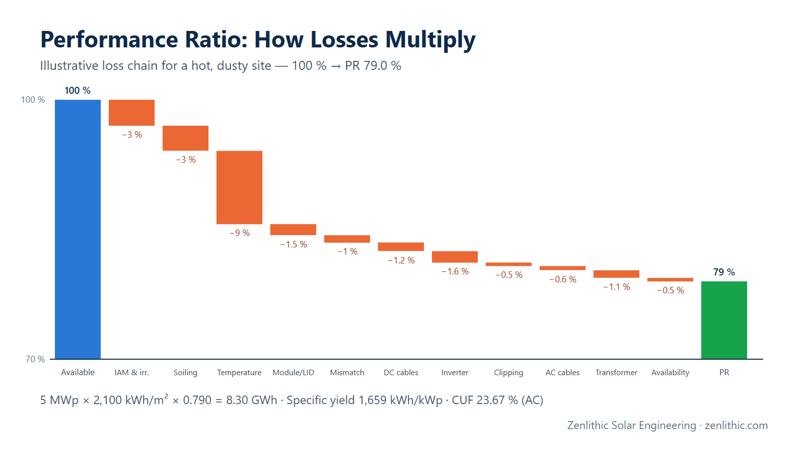
- Higher ratios raise CUF on AC capacity (see PR, CUF and generation calculation) because the inverter spends more hours near full load.
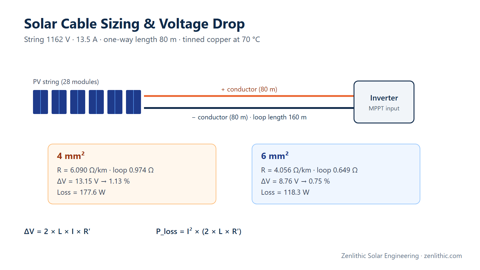
- The chosen strings per inverter set the DC cable layout and trench lengths (cable sizing guide).
- On land-constrained sites, the DC capacity may be limited by available area (see row spacing, pitch and GCR).
Design Considerations
- Temperature derating: many inverters deliver rated power only up to a specified ambient (check the derating curve). In hot regions the effective AC capacity at midday may be lower than the nameplate.
- Maximum DC input power: some inverters specify a maximum DC power or maximum recommended DC/AC ratio — exceeding it can void warranties.
- String vs central inverters: string inverters simplify O&M and MPPT granularity; central inverters allow higher ratios via combiners and suit large, uniform sites.
- Module degradation: DC output falls over the plant life, so clipping falls too — lifetime energy favours a slightly higher initial ratio.
- Battery storage (DC-coupled): clipped energy can be captured by a DC-coupled battery, changing the optimum ratio.
- Grid code: reactive power, ramp-rate and export-limit requirements affect inverter sizing and the plant controller.
Common Mistakes
- Choosing a DC/AC ratio from a rule of thumb without simulating the site's irradiance distribution.
- Ignoring the inverter's temperature derating, overestimating midday AC output in hot climates.
- Sizing inverters on kW and forgetting the kVA needed for reactive power.
- Forgetting that inputs per MPPT and MPPT current can cap the achievable ratio.
- Comparing CUF values without stating whether they are on AC or DC capacity.
- Treating clipping as a "failure" — moderate clipping at an optimised ratio is expected and economic.
Key Notes
- DC/AC ratio = kWp (STC) ÷ inverter kW (AC).
- Clipping starts roughly at G_clip = 1000 / (R × η × k_DC) W/m².
- The optimum ratio is site- and price-specific; typical ranges are industry practice, not requirements.
- Inverter hardware (inputs, MPPT current, max DC power) may limit the ratio before economics do.
- Reactive-power capability requires kVA headroom above the kW rating.
Engineer's Checklist
- AC export capacity and POI reactive-power requirement confirmed
- Inverter temperature derating checked at site maximum ambient
- Inverter kVA ≥ kW / pf required at POI (or active-power reduction accepted)
- Strings per MPPT within current and short-circuit limits
- Maximum achievable ratio calculated from inverter inputs
- Target ratio within inverter maximum DC input / manufacturer recommendation
- Clipping threshold estimated; PVsyst overload loss quantified
- Energy gain vs added DC cost compared for at least three ratios
- Final configuration recorded in DBR, SLD and string layout
FAQ
What is a good DC/AC ratio for a solar plant?
There is no universal value. Many utility-scale plants in sunny regions use roughly 1.2–1.45, but the right ratio comes from an hourly simulation of the specific site, inverter and tariff.
Does a higher DC/AC ratio damage the inverter?
No, provided the inverter's maximum DC voltage, maximum input current, maximum short-circuit current and maximum DC power are respected. The inverter simply limits its output (clips) when available DC power exceeds its AC rating.
How do I calculate clipping losses?
Estimate the clipping threshold with G_clip = 1000 / (R × η × k_DC), then run an hourly simulation (for example PVsyst) to find how much energy occurs above the inverter limit. PVsyst reports it as inverter overload loss.
Why is my plant CUF higher than my PR suggests?
CUF on AC capacity increases with the DC/AC ratio because more energy is produced per kW of inverter. PR is referenced to DC capacity and irradiance, so it does not rise the same way.
Should inverters be sized in kW or kVA?
Both. Active power (kW) sets energy delivery; apparent power (kVA) must cover the reactive power required by the grid code at the point of interconnection.
What is the difference between Euro efficiency and CEC efficiency?
Both are weighted averages of part-load efficiencies with different weightings. Euro efficiency weights 50 % load heavily; CEC weights 75 % load heavily. Compare inverters using the same metric.
Conclusion
Inverter sizing starts from the grid-connection capacity and ends with a site-specific DC/AC ratio confirmed by simulation. The worked example shows two practical lessons: clipping starts at an irradiance you can estimate in one line, and inverter input hardware can cap the ratio before economics do. With the configuration fixed, the next step is cable design and losses.
Related reading: Solar string sizing calculation · Solar cable sizing and voltage drop · PR, CUF and generation calculation
Need professional solar PV design, PVsyst simulation, AutoCAD drawings or electrical design support? Zenlithic provides solar design consultancy and engineering support for rooftop, C&I and utility-scale projects — inverter sizing, DC/AC optimisation, SLDs and DBR documentation. Explore Zenlithic Solar or contact our engineering team.