On a ground-mounted plant, every row of modules casts a shadow on the row behind it when the sun is low. Place the rows too close and the plant loses energy every winter morning and evening; place them too far apart and the project needs more land, longer cables and more fencing. Row spacing — expressed as pitch and ground coverage ratio (GCR) — is the geometric trade-off between shading loss and land use.
This guide derives the calculation from sun position and works a complete example for a fixed-tilt plant near Jaipur (26.9° N).
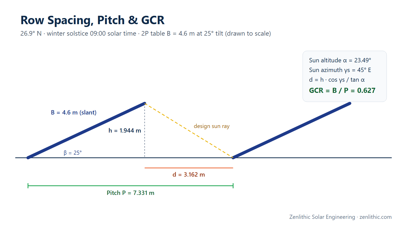
Quick answer: clear row spacing d = h × cos γs / tan α, where h is the table's vertical rise and α and γs are the sun's altitude and azimuth at your design hour (commonly 9:00 or 15:00 solar time on 21 December). Pitch = table horizontal depth + d, and GCR = table slant width ÷ pitch. At 26.9° N, a 4.6 m table tilted 25° needs d = 3.16 m, a 7.33 m pitch and a GCR of 0.627.
Introduction
Beginner understanding: Tilted solar tables are like a row of slanted walls. When the sun is low in the sky, the shadow of one wall can reach the next. Engineers pick the time of year and time of day when shadows are longest that they still want to avoid — commonly the shortest day of the year between 9 AM and 3 PM — and space the rows so that, at those times, the shadow just reaches the bottom of the next row.
Engineering understanding: The unshaded inter-row distance is the projection, perpendicular to the rows, of the shadow cast by the table's vertical height at the design sun position (altitude α, azimuth γs). Pitch = table horizontal depth + shadow-free spacing. GCR = collector slant width / pitch. The design window is a project choice (a common practice is 9:00–15:00 solar time on the winter solstice); the final choice balances shading loss (from PVsyst) against land and BOS cost.
What is it?
| Term | Definition |
|---|---|
| Tilt (β) | Angle of the module plane from horizontal |
| Collector width (B) | Slant length of the table from lower to upper edge |
| Table height difference (h) | Vertical rise of the table: h = B sin β |
| Inter-row spacing (d) | Clear ground distance between rows (shadow-free distance) |
| Pitch (P) | Distance between the same point on adjacent rows: P = B cos β + d |
| GCR | Collector width / pitch = B / P |
| Solar altitude (α) | Angle of the sun above the horizon |
| Solar azimuth (γs) | Horizontal angle of the sun from due south (northern hemisphere) |
Why is it important?
- Energy: inter-row shading causes both irradiance loss and electrical loss. Even partial shading of the bottom cells can cut a string's output far more than the shaded area suggests, which is why bypass-diode behaviour and module orientation matter.
- Land: pitch directly sets MWp per acre — often the deciding factor for land-constrained projects.
- Cost: tighter pitch shortens DC/AC cables, roads and fencing per MWp.
- Bankability: shading assumptions feed straight into the PVsyst loss diagram and the generation estimate.
When is it used?
- In land feasibility, to estimate capacity per acre.
- In layout design, to fix table spacing in the AutoCAD array layout.
- In PVsyst, to model row-to-row (mutual) shading and confirm the loss.
Where is it used?
Fixed-tilt ground-mounted plants and flat-roof C&I systems with tilted racks. (Single-axis trackers use a similar GCR concept, but shading is managed by backtracking algorithms.)
How does it work?
Sun position depends on latitude φ, the solar declination δ (day of year) and the hour angle ω (time from solar noon, 15° per hour):
sin α = sin φ sin δ + cos φ cos δ cos ω
sin γs = cos δ sin ω / cos α           (γs from south; negative = east/morning)
At the winter solstice δ ≈ −23.44° (northern hemisphere). The shadow of a height h falls a horizontal distance h / tan α in the direction away from the sun; its component perpendicular to east–west rows is:
d = h × cos γs / tan α
Required Input Data
| Input | Example |
|---|---|
| Site latitude φ | 26.9° N (Jaipur) |
| Design day and window | Winter solstice, 9:00–15:00 solar time (common practice, project choice) |
| Table configuration | 2 modules in portrait (2P) |
| Collector width B | 4.6 m (2 × ≈2.28 m modules + gap) |
| Tilt β | 25° (compare 15° and 20°) |
| Row orientation | East–west rows, modules facing due south |
| Terrain | Flat |
Step-by-Step Design Process
- Fix latitude, row orientation and table geometry (B, portrait/landscape).
- Choose the design window (day and hours) with the client/project team.
- Calculate solar altitude and azimuth at the limiting times (window start/end).
- Calculate the table's vertical height h = B sin β.
- Calculate shadow-free spacing d = h cos γs / tan α.
- Calculate pitch P = B cos β + d and GCR = B / P.
- Check shading at noon and other times; repeat for alternative tilts.
- Model the layout in PVsyst (near-shading scene) to quantify annual shading loss.
- Estimate land density and finalise the pitch with the client based on energy vs land.
Formula
Declination (winter solstice): δ ≈ −23.44°
Hour angle: ω = 15° × (solar time − 12 h)
sin α = sin φ sin δ + cos φ cos δ cos ω
sin γs = cos δ sin ω / cos α
Noon altitude: α_noon = 90° − φ + δ
h = B sin β
d = h × cos γs / tan α
P = B cos β + d
GCR = B / P
Numerical Example
Site at φ = 26.9° N, winter solstice, 9:00 solar time (ω = −45°), 2P tables with B = 4.6 m, tilt β = 25°, flat ground, rows running east–west.
Engineering Calculation
Step 1 — Sun position at 9:00 on 21 December
sin φ = sin 26.9° = 0.45243      cos φ = 0.89180
sin δ = sin(−23.44°) = −0.39778  cos δ = 0.91748
cos ω = cos(−45°) = 0.70711      sin ω = −0.70711

sin α = (0.45243)(−0.39778) + (0.89180)(0.91748)(0.70711)
      = −0.17997 + 0.57856 = 0.39859
α = 23.49°

sin γs = (0.91748)(−0.70711) / cos 23.49° = −0.64876 / 0.91713 = −0.70738
γs = −45.0°   (45° east of south)
By symmetry, 15:00 gives the same altitude with γs = +45.0° (west of south).
Step 2 — Table height
h = 4.6 × sin 25° = 4.6 × 0.42262 = 1.944 m
Step 3 — Shadow-free spacing
d = h × cos γs / tan α = 1.944 × 0.70686 / 0.43461 = 1.944 × 1.6264 = 3.162 m
Step 4 — Pitch and GCR
Horizontal table depth = 4.6 × cos 25° = 4.6 × 0.90631 = 4.169 m
P   = 4.169 + 3.162 = 7.331 m
GCR = 4.6 / 7.331 = 0.627
Step 5 — Noon check
α_noon = 90° − 26.9° + (−23.44°) = 39.66°
Shadow = 1.944 / tan 39.66° = 1.944 / 0.8290 = 2.345 m  < 3.162 m ✅ (no shading at noon)
Step 6 — Effect of tilt (same B, same design window)
| Tilt β | h (m) | Spacing d (m) | Pitch P (m) | GCR |
|---|---|---|---|---|
| 15° | 1.191 | 1.936 | 6.380 | 0.721 |
| 20° | 1.573 | 2.559 | 6.881 | 0.668 |
| 25° | 1.944 | 3.162 | 7.331 | 0.627 |
Lower tilt allows a tighter pitch (more MWp per acre) but typically collects slightly less annual irradiation at this latitude and soils faster. The energy-optimal fixed tilt for annual yield is usually near — often a little below — the latitude; confirm with PVsyst's orientation optimisation for your site and weigh it against land, structure and wind-load cost.
Step 7 — Land density (array area only)
Assume a 560 Wp module of 2.278 m × 1.134 m (2.583 m²):
Module power density = 560 / 2.583 = 216.8 W/m² of module area
Array ground density ≈ GCR × 216.8 = 0.627 × 216.8 = 136 W/m²
Per acre (4,046.86 m²) = 136 × 4,046.86 ≈ 550 kWp ≈ 0.55 MWp/acre (array footprint only)
Total land is higher: add roads, drainage, inverter/transformer areas, boundary setbacks, and any unusable terrain according to the actual layout.
Practical Solar Application
- The pitch from this calculation becomes the row spacing in the AutoCAD array layout and the near-shading scene in PVsyst.
- PVsyst's "linear shading" and "electrical effect according to module strings" options quantify how much the chosen pitch costs in annual energy — this, not the geometric rule alone, is what goes into the generation estimate.
- Row length and table configuration must be consistent with the string length so strings are not split awkwardly between tables.
- Pitch sets trench and cable run lengths in the cable design.
Design Considerations
- Design window is a project decision. 9:00–15:00 on the winter solstice is common practice, not a standard; some projects accept more shading for more capacity on limited land.
- Terrain slope: a slope rising towards the back rows (north in the northern hemisphere) increases the required pitch; a south-facing slope reduces it. Model real terrain in 3D rather than assuming flat ground.
- Module orientation: landscape layouts (e.g. 4L) can reduce the electrical impact of bottom-edge shading compared with portrait, because each shaded row affects fewer bypass-diode substrings.
- Bifacial modules: rear-side gain depends on row spacing, table height and ground albedo — wider pitch and higher clearance increase it.
- Cleaning and access: very tight pitch can make vehicle-based cleaning and maintenance difficult.
- Far shading: trees, hills or buildings on the horizon need a separate horizon profile in PVsyst.
Common Mistakes
- Using the shadow length along the sun's direction instead of its component perpendicular to the rows (forgetting cos γs), which over-spaces the rows.
- Using local clock time instead of solar time.
- Mixing up pitch (row-to-row) and spacing (clear gap).
- Computing GCR with the horizontal table depth instead of the slant collector width.
- Assuming flat terrain on sloped land.
- Treating the geometric no-shading rule as the final answer without checking annual shading loss in PVsyst.
Key Notes
- d = h cos γs / tan α; P = B cos β + d; GCR = B / P.
- At 26.9° N, 9:00 on the winter solstice: α = 23.49°, γs = 45° east of south.
- The example gives P = 7.33 m and GCR = 0.627 at 25° tilt.
- Lower tilt → tighter pitch → more MWp per acre, with an energy trade-off.
- The design window and acceptable shading are project decisions.
Engineer's Checklist
- Latitude, row orientation and table geometry confirmed
- Design window agreed and documented
- Sun altitude and azimuth calculated in solar time
- Shadow component perpendicular to rows used
- Pitch and GCR calculated for candidate tilts
- Noon and edge-of-window cases checked
- Terrain slope and far shading considered
- PVsyst near-shading model built and annual loss quantified
- Land density and total land (with roads, setbacks) estimated
- Final pitch reflected in the AutoCAD layout and DBR
FAQ
How do I calculate row spacing for solar panels?
Calculate the table's vertical height (h = B sin β), find the sun's altitude and azimuth at your design time, and use d = h × cos γs / tan α for the clear spacing. Add the table's horizontal depth to get the pitch.
What is GCR in solar?
Ground coverage ratio is the collector (slant) width divided by the row pitch. A GCR of 0.627 means the tables cover about 63 % of the ground measured along the pitch direction.
Why is the winter solstice used for shadow analysis?
At the winter solstice the sun is lowest in the sky at midday in the northern hemisphere, so shadows are longest. Spacing that avoids shading then avoids it for the rest of the year within the same daily window.
What tilt angle should I use for a fixed solar plant?
For annual energy, the optimum fixed tilt is usually near, often slightly below, the site latitude. The final tilt also considers row spacing, land, wind loads and soiling, and should be confirmed with simulation.
Does row spacing affect bifacial module yield?
Yes. Wider spacing and higher mounting let more reflected light reach the module rear, increasing bifacial gain, at the cost of more land per MWp.
How many MW can be installed per acre?
It depends on module efficiency, GCR and non-array land use. In the example, the array footprint alone gives about 0.55 MWp per acre; roads, setbacks and equipment areas reduce the overall figure.
Conclusion
Row spacing follows directly from sun geometry: with the winter-solstice sun at 23.49° altitude and 45° azimuth at 9:00 solar time, a 4.6 m table at 25° tilt needs 3.16 m clear spacing, a 7.33 m pitch and a GCR of 0.627 at Jaipur's latitude. The geometry gives the starting point; PVsyst's shading analysis and the land–energy trade-off decide the final layout.
Related reading: PR, CUF and generation calculation · Solar string sizing calculation · Solar cable sizing and voltage drop
Need professional solar PV design, PVsyst simulation, AutoCAD drawings or electrical design support? Zenlithic provides solar design consultancy and engineering support for rooftop, C&I and utility-scale projects — shadow analysis, tilt and pitch optimisation, array layouts and land assessment. Explore Zenlithic Solar or contact our engineering team.