Cables are a large share of a PV plant's balance-of-system cost and a permanent source of energy loss. Undersize them and they overheat or waste energy for 25 years; oversize them and the project pays for copper or aluminium it does not need. A correct cable size satisfies three independent checks: current-carrying capacity (after derating), voltage drop / loss, and short-circuit withstand.
This guide covers DC string cables, LV AC cables and HT cables, with complete worked examples.
Quick answer: a solar cable must pass three checks — derated current-carrying capacity ≥ design current (1.25 × Isc for DC strings under IEC 62548), voltage drop within the project limit (Indian utility specifications typically target ≲ 1.5 % DC and ≲ 1 % LT AC), and short-circuit withstand (A ≥ I_k√t / k). For a 28-module, 13.5 A string over 80 m, 6 mm² gives 0.75 % drop against 1.13 % for 4 mm².
Introduction
Beginner understanding: Every cable has resistance. When current flows through it, some voltage is "lost" along the cable and turns into heat. A thicker cable (bigger cross-section in mm²) has lower resistance, so it loses less and runs cooler — but costs more. Cable sizing means choosing the smallest cable that stays cool enough, loses little enough energy and can survive a short circuit.
Engineering understanding: Cable selection verifies that (1) the derated current-carrying capacity I_z ≥ design current I_B, (2) voltage drop and power loss at the design operating point are within the project's limits, and (3) the conductor (and screen/armour for HT) can withstand the prospective fault current for the protection clearing time. The governing check differs by circuit: DC string cables are usually governed by voltage drop, LV AC feeders by ampacity or voltage drop, and HT cables often by short-circuit withstand.
What is it?
| Circuit | Typical cable | Typical governing check |
|---|---|---|
| Module → string / inverter input (DC) | Single-core PV cable to EN 50618 / IEC 62930, tinned copper, 4–6 mm² | Voltage drop / loss |
| Combiner box → central inverter (DC) | Single-core Al or Cu, 1.5 kV DC rated, 95–400 mm² | Voltage drop and ampacity |
| String inverter → LV panel / transformer (AC) | LV XLPE, Al or Cu, 3½ or 4 core, or single cores | Ampacity and voltage drop |
| Transformer HV → switchgear / pooling (HT) | 11/22/33 kV XLPE, Al | Short-circuit withstand and ampacity |
Why is it important?
- Safety: an undersized conductor overheats; insulation ages fast and can fail.
- Energy: cable loss is paid every operating hour for the plant's life.
- Protection: the cable must survive a fault until the protection device clears it.
- Compliance: wiring design must follow the applicable standards (for PV installations, IEC 60364-7-712 and IEC 62548; for current-carrying capacity, IEC 60364-5-52; conductor resistances, IEC 60228) and the project specification.
When is it used?
- At DBR stage, when cable schedules, voltage-drop limits and cable types are fixed.
- During layout, as trench routes and lengths become known.
- In PVsyst, where DC and AC ohmic losses are entered from the cable design.
Where is it used?
Every DC and AC circuit: rooftop string cables, C&I LT feeders, utility-scale DC trunk cables, inverter AC cables, transformer LV links and HT evacuation cables.
How does it work?
A conductor's resistance depends on material, cross-section and temperature:
R_T = R_20 × [1 + α × (T − 20)]
α (copper) = 0.00393 /°C      α (aluminium) = 0.00403 /°C
Current-carrying capacity is published for reference installation conditions and must be corrected for the real ambient temperature, grouping with other circuits, soil thermal resistivity (buried cables) and installation method.
Required Input Data
| Input | Source |
|---|---|
| Design current (Imp, Isc, inverter output current) | String design, inverter datasheet |
| System voltage (Vmp string, AC line voltage) | Design |
| Route length (one way) | Layout / cable schedule |
| Conductor resistance at 20 °C | IEC 60228 / cable datasheet |
| Reference current rating & installation method | Cable datasheet / IEC 60364-5-52 |
| Ambient / ground temperature, grouping, soil resistivity | Site data, layout |
| Allowed voltage drop / loss | Project specification (not a single universal standard) |
| Prospective fault current and clearing time | Short-circuit study / protection settings |
Step-by-Step Design Process
- Calculate the design current I_B for the circuit.
- Select cable type and installation method (free air, tray, conduit, buried).
- Apply derating factors (temperature, grouping, soil) to the reference rating: I_z = I_z0 × k_temp × k_group × k_soil.
- Choose the smallest size with I_z ≥ I_B.
- Calculate voltage drop and power loss; increase size if the project limit is exceeded.
- Check short-circuit withstand (and, for HT, screen/armour fault rating).
- Check protection coordination (fuse/breaker rating between I_B and I_z where applicable).
- Record in the cable schedule and use the losses in PVsyst.
Formula
DC voltage drop (two conductors, go and return):
ΔV = 2 × L × I × R'          R' in Ω/m at operating temperature
ΔV% = ΔV / V × 100
P_loss = I² × (2 × L × R')
Three-phase AC voltage drop:
ΔV = √3 × I × L × (R' cos φ + X' sin φ)
P_loss = 3 × I² × R' × L
Three-phase current:
I = P / (√3 × V_LL × pf)
Derated capacity:
I_z = I_z0 × k_temp × k_group (× k_soil for buried cables) require I_z ≥ I_B
Short-circuit (adiabatic) withstand — minimum conductor area:
A ≥ I_k × √t / k
k (XLPE, copper) = 143     k (XLPE, aluminium) = 94     (90 °C → 250 °C)
The k values are the standard adiabatic constants for XLPE-insulated conductors (IEC 60364-5-54 / IEC 60949 method).
Numerical Example
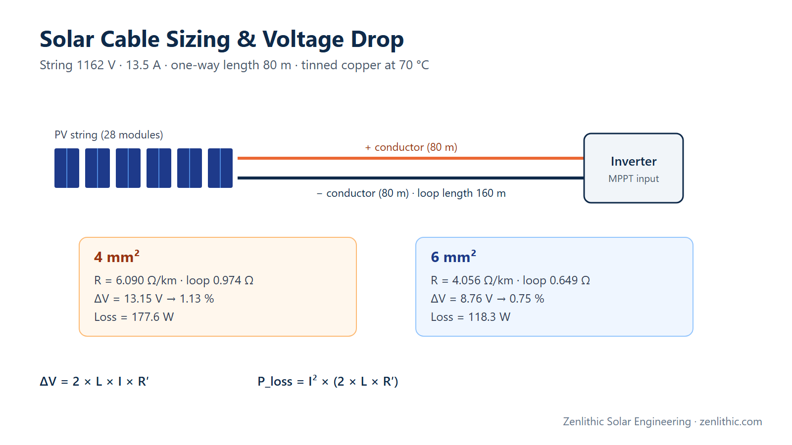
Example A — DC string cable: string of 28 modules, Vmp = 1162 V (STC), Imp = 13.5 A, Isc = 14.2 A (from our string sizing example); one-way route length 80 m; tinned copper PV cable, conductor temperature 70 °C; compare 4 mm² and 6 mm².
Example B — LV AC cable: 320 kW string inverter at 800 V three-phase, 150 m to the LV panel, aluminium XLPE 240 mm²; pf = 1 and pf = 0.95.
Example C — HT cable fault withstand: 33 kV system, prospective fault 25 kA, clearing time 1 s, aluminium XLPE.
Engineering Calculation
Example A — DC string cable
Resistance at 20 °C (IEC 60228, class 5 tinned copper): 4 mm² = 5.09 Ω/km, 6 mm² = 3.39 Ω/km.
Temperature factor at 70 °C = 1 + 0.00393 × (70 − 20) = 1.1965

4 mm²: R' = 5.09 × 1.1965 = 6.090 Ω/km
       loop resistance = 6.090 × 0.160 km = 0.9744 Ω
       ΔV = 13.5 × 0.9744 = 13.15 V   → 13.15 / 1162 = 1.13 %
       P_loss = 13.5² × 0.9744 = 177.6 W

6 mm²: R' = 3.39 × 1.1965 = 4.056 Ω/km
       loop resistance = 4.056 × 0.160 km = 0.6490 Ω
       ΔV = 13.5 × 0.6490 = 8.76 V    → 8.76 / 1162 = 0.75 %
       P_loss = 13.5² × 0.6490 = 118.3 W
String power at STC = 1162 V × 13.5 A = 15,687 W, so the loss percentages equal the voltage-drop percentages (1.13 % and 0.75 %), as expected for DC.
Ampacity check. Design current (short-circuit based, IEC 62548 practice): I_B = 1.25 × 14.2 = 17.75 A. (Under the US NEC 690.8, conductor sizing uses 1.56 × Isc = 22.19 A.) Suppose the cable datasheet rates 4 mm² at I_z0 = 55 A for a single cable in free air at the reference ambient (example datasheet value — use your manufacturer's table and reference conditions), and six circuits are bunched on a tray (grouping factor 0.57 from IEC 60364-5-52, Table B.52.17):
I_z = 55 × 0.57 = 31.4 A ≥ 17.75 A ✅
Interpretation: both sizes pass ampacity easily; voltage drop governs. If the project limits DC string drop to 1 %, 4 mm² fails at 80 m and 6 mm² passes. Rearranging, the maximum one-way length for 1 % with 4 mm² is:
L_max = (0.01 × 1162) / (2 × 13.5 × 6.090 × 10⁻³) = 11.62 / 0.16443 = 70.7 m
Example B — LV AC cable (240 mm² Al, 150 m)
I (pf 1) = 320,000 / (√3 × 800 × 1.0) = 230.9 A
R_20 (Al 240 mm², IEC 60228) = 0.125 Ω/km
R' at 90 °C = 0.125 × [1 + 0.00403 × 70] = 0.1603 Ω/km   (skin effect neglected)
X' = 0.08 Ω/km (typical value — take from the cable datasheet)

pf = 1:    ΔV = √3 × 230.9 × 0.150 × (0.1603 × 1 + 0.08 × 0) = 9.62 V → 1.20 %
           P_loss = 3 × 230.9² × 0.1603 × 0.150 = 3,846 W → 1.20 % of 320 kW

pf = 0.95: I = 320,000 / (√3 × 800 × 0.95) = 243.1 A,  sin φ = 0.3122
           ΔV = √3 × 243.1 × 0.150 × (0.1603 × 0.95 + 0.08 × 0.3122) = 11.19 V → 1.40 %
Using 90 °C (the maximum XLPE operating temperature) gives a conservative loss figure; at typical loading the conductor runs cooler. Supplying reactive power increases current and therefore both voltage drop and loss for the same active power.
Interpretation against a typical 1 % LT AC limit: 240 mm² at 150 m fails (1.20 % at pf 1). Options are a larger conductor or a shorter run. With 300 mm² Al (R_20 = 0.100 Ω/km, IEC 60228 → 0.1282 Ω/km at 90 °C):
ΔV = √3 × 230.9 × 0.150 × 0.1282 = 7.69 V → 0.96 % ✅
Example C — HT short-circuit withstand
A ≥ 25,000 × √1 / 94 = 266 mm²  → select 300 mm² Al (or larger if ampacity requires)
Check: 300 × 94 = 28,200 A for 1 s ≥ 25,000 A  ✅
The metallic screen must be checked separately against the earth-fault current and clearing time.
Practical Solar Application
- DC and AC ohmic losses from this calculation are entered in PVsyst's loss settings (or PVsyst computes them from the wiring definition).
- Maximum string cable lengths define where inverters or combiner boxes sit in the DC layout, which in turn affects trench length.
- For string inverters distributed in the array, most cable cost moves to the AC side; for central inverters, DC trunk cables dominate.
- The HT cable fault rating links to the short-circuit study and protection relay settings in the SLD.
Design Considerations
- Voltage-drop limits are project requirements. Indian utility specifications typically target about 1.5 % for DC and 1 % for LT AC; other markets and tenders differ. Always use the value in the tender or DBR — there is no single universal PV standard value.
- Use resistance at operating temperature, not at 20 °C, for loss calculations.
- Annual energy loss is lower than the STC-point percentage, because loss scales with current squared and most operating hours are below rated current; PVsyst calculates the annual figure.
- Copper vs aluminium: aluminium has about 1.64 × the resistivity of copper (0.0283 vs 0.0172 Ω·mm²/m at 20 °C), so it needs a larger cross-section for the same resistance, but it is lighter and usually cheaper. It needs correct terminations (bimetallic lugs, torque). PV string cables to EN 50618 are tinned copper.
- Buried cables: soil thermal resistivity and depth change ratings significantly; get site soil data.
- DC cables must be rated for DC system voltage (for example 1.5 kV DC for 1500 V systems).
Common Mistakes
- Using one-way length instead of loop length (2 × L) for DC voltage drop.
- Using 20 °C resistance for loss calculations.
- Ignoring grouping factors where many string cables share a tray or trench.
- Sizing AC cables at pf = 1 when the plant must supply reactive power.
- Skipping the short-circuit withstand check on HT cables and screens.
- Quoting a voltage-drop limit as a "standard" when it is a project specification.
Key Notes
- Three checks: ampacity (after derating), voltage drop/loss, short-circuit withstand.
- DC string cables: usually governed by voltage drop.
- For DC, % voltage drop = % power loss at that operating point.
- A ≥ I_k√t / k with k = 143 (Cu XLPE) and 94 (Al XLPE).
- Always use manufacturer data for current ratings and reactance.
Engineer's Checklist
- Design current defined per circuit (including 1.25 × Isc for DC)
- Installation method and derating factors documented
- I_z ≥ I_B after derating
- Voltage drop and loss within the project specification
- Resistance corrected to operating temperature
- Reactive-power current included for AC feeders
- Short-circuit withstand checked (conductor and screen/armour)
- Cable DC/AC voltage rating suitable (1.5 kV DC for 1500 V systems)
- Terminations suitable for conductor material
- Cable schedule updated; losses entered in PVsyst
FAQ
How do I calculate voltage drop in a DC solar cable?
ΔV = 2 × L × I × R', where L is the one-way length, I the operating current and R' the resistance per metre at operating temperature. Divide by the string voltage for the percentage.
What is the maximum allowed voltage drop in a solar plant?
It is set by the project specification rather than one universal standard. Indian utility specifications typically target about 1.5 % for DC and 1 % for LT AC — always follow the tender or DBR value.
Why are solar string cables usually 4 mm² or 6 mm²?
String currents are only about 10–20 A, so ampacity is rarely the limit. Voltage drop over the string route length decides between 4 mm² and 6 mm².
Should I use copper or aluminium cables in a solar plant?
String cables are tinned copper (EN 50618 / IEC 62930). For large DC trunk, LV AC and HT cables, aluminium is common because it is lighter and cheaper for the same current, at the cost of a larger cross-section and careful terminations.
What is the k factor in the short-circuit formula?
k is a material/insulation constant for the adiabatic temperature rise from the maximum operating temperature to the maximum short-circuit temperature: 143 for copper XLPE and 94 for aluminium XLPE (90 °C to 250 °C).
Why does reactive power increase cable losses?
For the same active power, a lower power factor means higher current. Losses scale with current squared, so both voltage drop and loss rise.
Conclusion
Cable sizing is three checks, not one. In the worked examples, the DC string cable was governed by voltage drop (6 mm² needed for 1 % at 80 m), the LV feeder showed how reactive power raises drop from 1.20 % to 1.40 %, and the HT cable was sized by fault withstand. Feed the resulting losses into the energy model to see their effect on PR.
Related reading: Solar string sizing calculation · DC/AC ratio and inverter sizing · PR, CUF and generation calculation
Need professional solar PV design, PVsyst simulation, AutoCAD drawings or electrical design support? Zenlithic provides solar design consultancy and engineering support for rooftop, C&I and utility-scale projects — cable schedules, voltage-drop studies, HT/LT design and SLDs. Explore Zenlithic Solar or contact our engineering team.