String sizing is the first calculation where a PV design can become unsafe or quietly lose energy. Put too many modules in series and the string voltage on a cold morning can exceed the inverter's or module's maximum DC voltage. Put too few and, on a hot afternoon, the string voltage can fall below the inverter's MPPT range, so the inverter cannot track the maximum power point.
This guide explains the method engineers use, then works through a complete example for a 1500 V plant, comparing 26 and 28 modules per string.
Quick answer: maximum modules per string = floor(maximum DC voltage ÷ module Voc at the site's record-low temperature); minimum = ceil(inverter full-power MPPT minimum ÷ module Vmp at the highest cell temperature). For a 560 Wp module (Voc 49.5 V, βVoc −0.25 %/°C) at a site with a 2 °C record low on a 1500 V inverter, Voc rises to 52.35 V, so at most 28 modules fit — and both 26 and 28 stay inside the MPPT window on a 75 °C afternoon.
Introduction
Beginner understanding: Solar modules in a string are connected in series, like batteries in a torch. Voltages add up; the current stays the same. A module's voltage goes up when it is cold and down when it is hot. String sizing means choosing how many modules to connect in series so the string voltage always stays inside the limits of the inverter and the modules, in every weather condition the site will see.
Engineering understanding: String sizing selects the number of series-connected modules, N, such that:
- the temperature-corrected open-circuit voltage at the lowest expected ambient temperature does not exceed the maximum DC voltage of the inverter or the maximum system voltage of the module, and
- the temperature-corrected maximum-power voltage at the highest expected cell temperature stays at or above the inverter's minimum MPPT voltage (preferably the full-power MPPT range), and
- the number of strings in parallel on each MPPT input respects the inverter's maximum input current and maximum short-circuit current.
What is it?
A string is a group of PV modules connected in series (positive of one module to negative of the next). String sizing is the calculation of:
- Modules per string (N) — set by voltage limits.
- Strings per MPPT / per inverter — set by current limits and the target DC/AC ratio.
| Parameter | Symbol | Behaviour in series | Driven by |
|---|---|---|---|
| Open-circuit voltage | Voc | Adds (N × Voc) | Cell temperature (strongly), irradiance (weakly, logarithmic) |
| Maximum-power voltage | Vmp | Adds (N × Vmp) | Cell temperature |
| Short-circuit current | Isc | Same as one module | Irradiance (proportional) |
| Maximum-power current | Imp | Same as one module | Irradiance |
Why is it important?
- Safety: exceeding the maximum DC voltage can damage inverter input stages and violate the module's insulation rating (module maximum system voltage is qualified under IEC 61730). Voltage limits are hard limits — they are not an energy trade-off.
- Energy yield: if the string Vmp drops below the MPPT range in hot weather, the inverter operates off the maximum power point and energy is lost exactly when irradiance is high.
- Cost: longer strings mean fewer strings, fewer string cables, fewer combiner/inverter inputs and lower DC cable losses. Engineers therefore want the longest string that is still safe.
When is it used?
- During concept design, once the module and inverter have been shortlisted.
- In the detailed design / DBR stage, where the string configuration is frozen and drawn in the string layout.
- When changing the module or inverter model — a different Voc or temperature coefficient can change the allowed string length.
- In PVsyst, which performs the same checks and warns when the configuration violates voltage limits.
Where is it used?
Every grid-connected PV system: residential and C&I rooftops (typically 1000 V or 1100 V systems) and ground-mounted/utility-scale plants (typically 1500 V systems). The method is the same; only the voltage limits and climate data change.
How does it work?
Module voltage changes with cell temperature according to the datasheet temperature coefficient. Datasheets quote Voc and Vmp at Standard Test Conditions (STC): 1000 W/m², 25 °C cell temperature, AM1.5 spectrum.
- Maximum voltage case (cold): the highest Voc occurs at the lowest cell temperature. At sunrise on the coldest day of the year the modules are close to ambient temperature, the inverter is not yet loading the string, and the string sits at open circuit. The calculation therefore uses Voc at the lowest expected ambient temperature. (US NEC 690.7 uses exactly this approach — Voc corrected to the lowest expected ambient temperature.)
- Minimum voltage case (hot): the lowest Vmp occurs at the highest cell temperature — a hot, sunny afternoon when the modules may be 25–35 °C above ambient.
Because Voc also depends slightly on irradiance (it falls at low light), using STC irradiance together with the minimum temperature is a conservative assumption for the maximum-voltage check.
Required Input Data
| Input | Source | Example value used below |
|---|---|---|
| Module Voc, Vmp, Isc, Imp (STC) | Module datasheet | 49.5 V, 41.5 V, 14.2 A, 13.5 A |
| Voc temperature coefficient (βVoc) | Module datasheet | −0.25 %/°C (assumed, typical TOPCon) |
| Pmax temperature coefficient (γ) | Module datasheet | −0.29 %/°C (assumed) |
| Isc temperature coefficient (αIsc) | Module datasheet | +0.045 %/°C (assumed) |
| Module maximum system voltage | Module datasheet | 1500 V DC |
| Inverter maximum DC input voltage | Inverter datasheet | 1500 V |
| Inverter MPPT range (operating) | Inverter datasheet | 500–1500 V |
| Inverter full-power MPPT range | Inverter datasheet | 860–1300 V |
| Max input current per MPPT | Inverter datasheet | 30 A |
| Max short-circuit current per MPPT | Inverter datasheet | 50 A |
| Lowest expected ambient temperature | Long-term site data (e.g. record low from meteorological data) | 2 °C (assumed site) |
| Highest expected cell temperature | Max ambient + irradiance-driven rise | 75 °C (assumed: 45 °C ambient + ~30 °C) |
Note on the example inverter: the inverter values above are representative of current 1500 V string inverters, but they are an example. Always use the datasheet of the exact inverter model you are designing with.
Step-by-Step Design Process
- Collect module and inverter datasheet values (table above).
- Establish site temperatures: the lowest expected ambient (for Voc) and the highest expected cell temperature (for Vmp).
- Calculate the module Voc at minimum temperature.
- Calculate the maximum modules per string: N_max = floor(V_max,DC / Voc,cold), using the lower of the inverter maximum DC voltage and the module maximum system voltage.
- Calculate the module Vmp at maximum cell temperature.
- Calculate the minimum modules per string: N_min = ceil(V_MPPT,min / Vmp,hot) — ideally using the full-power MPPT lower limit.
- Check the cold-weather Vmp against the upper MPPT limit.
- Choose N between N_min and N_max, considering margin, cable losses and layout (table length, rows).
- Size strings per MPPT from the current limits.
- Record the configuration in the DBR, string layout and PVsyst model, and verify PVsyst reports no voltage warnings.
Formula
Temperature-corrected open-circuit voltage:
Voc(T) = Voc,STC × [1 + βVoc × (T − 25 °C)]
Temperature-corrected maximum-power voltage:
Vmp(T) = Vmp,STC × [1 + βVmp × (T − 25 °C)]
If the datasheet does not publish a Vmp coefficient, a common engineering approximation is:
βVmp ≈ γPmax − αIsc
This follows from P = V × I (so the relative power change ≈ relative voltage change + relative current change) and uses the Isc coefficient as a proxy for the Imp coefficient. It is an approximation, not a datasheet value — use the manufacturer's Vmp coefficient when available.
Cell temperature estimate (NOCT method):
T_cell ≈ T_ambient + (NOCT − 20 °C) / 800 W/m² × G
String limits:
N_max = floor( V_DC,max / Voc(T_min) )
N_min = ceil( V_MPPT,min / Vmp(T_cell,max) )
Where T is in °C, coefficients are in %/°C converted to per-unit (−0.25 %/°C = −0.0025 /°C).
Numerical Example
Module (STC): Voc = 49.5 V, Vmp = 41.5 V, Isc = 14.2 A, Imp = 13.5 A (≈ 560 Wp). Coefficients: βVoc = −0.25 %/°C, γPmax = −0.29 %/°C, αIsc = +0.045 %/°C. Site: T_min = 2 °C; T_cell,max = 75 °C. Inverter as in the input table.
Evaluate 26 modules per string and 28 modules per string.
Engineering Calculation
Step 1 — Voc at 2 °C
ΔT = 2 − 25 = −23 °C
Voc(2 °C) = 49.5 × [1 + (−0.0025)(−23)]
          = 49.5 × 1.0575
          = 52.35 V
Step 2 — Maximum modules per string
The limiting maximum DC voltage is 1500 V (inverter and module are both 1500 V).
N_max = floor(1500 / 52.35) = floor(28.65) = 28 modules
Step 3 — Vmp at 75 °C
βVmp ≈ −0.29 − 0.045 = −0.335 %/°C
ΔT = 75 − 25 = 50 °C
Vmp(75 °C) = 41.5 × [1 − 0.00335 × 50]
           = 41.5 × 0.8325
           = 34.55 V
Step 4 — Minimum modules per string (full-power MPPT lower limit 860 V)
N_min = ceil(860 / 34.55) = ceil(24.89) = 25 modules
Step 5 — Cold-weather Vmp (upper MPPT check) at an operating cell temperature of 10 °C on a cold, sunny day:
Vmp(10 °C) = 41.5 × [1 + 0.00335 × 15] = 41.5 × 1.0503 = 43.59 V
Step 6 — Compare the two configurations
| Check | Limit | 26 modules | 28 modules |
|---|---|---|---|
| String Voc at STC (25 °C) | — | 26 × 49.5 = 1287.0 V | 28 × 49.5 = 1386.0 V |
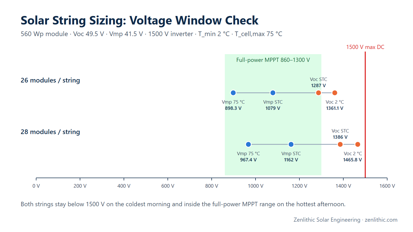
| String Voc at 2 °C | ≤ 1500 V | 26 × 52.35 = 1361.1 V ✅ | 28 × 52.35 = 1465.8 V ✅ |
| Margin to 1500 V | — | 138.9 V (9.3 %) | 34.2 V (2.3 %) |
| String Vmp at STC | — | 26 × 41.5 = 1079.0 V | 28 × 41.5 = 1162.0 V |
| String Vmp at 75 °C | ≥ 860 V (full power) | 26 × 34.55 = 898.3 V ✅ | 28 × 34.55 = 967.4 V ✅ |
| Margin above 860 V | — | 38.3 V (4.5 %) | 107.4 V (12.5 %) |
| String Vmp at 10 °C | ≤ 1300 V (full power) | 26 × 43.59 = 1133.3 V ✅ | 28 × 43.59 = 1220.5 V ✅ |
| String current (Imp / Isc) | per string | 13.5 A / 14.2 A | 13.5 A / 14.2 A |
| String power at STC | — | 26 × 560 = 14.56 kWp | 28 × 560 = 15.68 kWp |
| 29 modules (for reference) | ≤ 1500 V | — | 29 × 52.35 = 1518.2 V ❌ |
Step 7 — Strings per MPPT
Operating current: 2 strings × 13.5 A = 27.0 A ≤ 30 A  ✅
                   3 strings × 13.5 A = 40.5 A > 30 A  ❌ (current-limited)
Short-circuit:     2 strings × 14.2 A × 1.25 = 35.5 A ≤ 50 A  ✅
The 1.25 factor on Isc is the conventional allowance for irradiance above 1000 W/m² used for the maximum circuit current in IEC 62548 practice and NEC 690.8. In the US, NEC then applies a further 1.25 for conductor and fuse sizing, i.e. 1.25 × 1.25 × Isc = 1.56 × Isc (22.19 A for this module). Bifacial modules need an additional allowance for rear-side gain — follow the module manufacturer's guidance and the edition of IEC 62548 applicable to your project.
Result: 2 strings per MPPT. With a 12-MPPT inverter that is 24 strings per inverter:
26 modules: 24 × 14.56 kWp = 349.4 kWp per inverter
28 modules: 24 × 15.68 kWp = 376.3 kWp per inverter
Engineering interpretation
- Both 26 and 28 modules are technically suitable with these inputs: neither exceeds 1500 V at 2 °C, and both stay inside the full-power MPPT range at 75 °C and 10 °C.
- 28 modules is the maximum allowed and gives the best economics — about 7.1 % fewer strings for the same DC capacity (26/28 = 0.929), fewer string cables and lower DC ohmic loss (higher voltage, same current). Its cold-voltage margin is only 2.3 %, so it is only acceptable if the minimum-temperature figure is reliable (long-term record low, not an average winter minimum).
- 26 modules leaves a comfortable voltage margin but its hot-weather Vmp is only 4.5 % above the full-power MPPT limit. After DC cable voltage drop (typically 1–2 %) and module tolerance, it could approach the limit on the hottest days.
- A frequent engineering choice here would be 27 or 28 modules, decided by how much confidence you have in the site's record-low temperature data and your company's margin policy. That margin policy is a project/company requirement, not a standard.
Practical Solar Application
- The chosen N drives the mechanical table design — tables are usually built to hold one or two full strings (e.g. 28 modules in 2P × 14 or 1P × 28), so string length and table length are decided together.
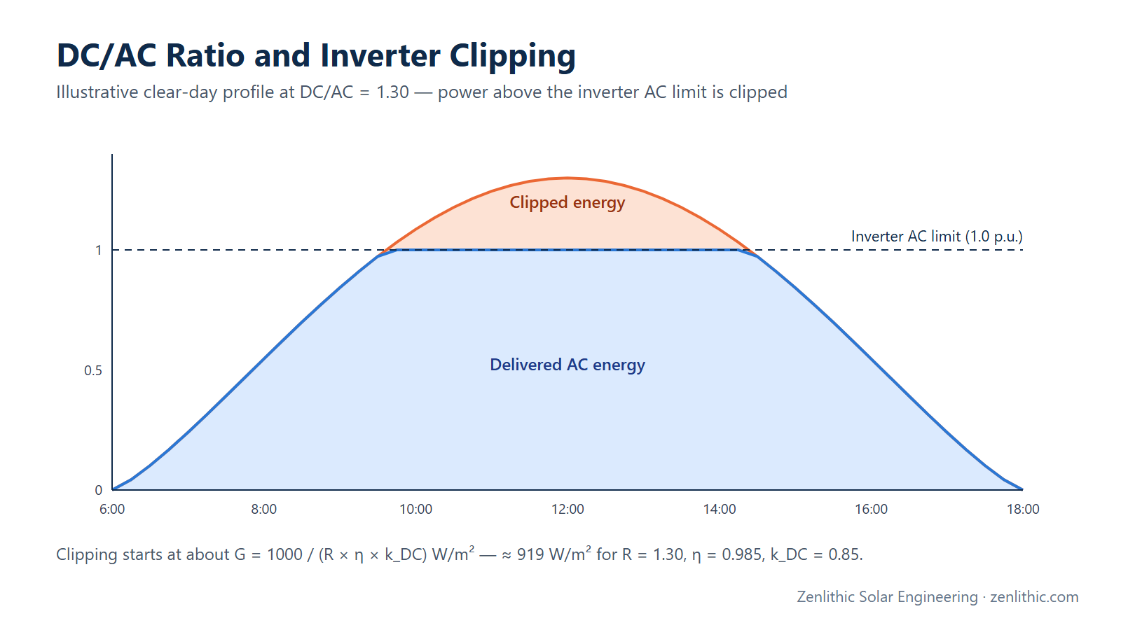
- It sets strings per inverter and therefore the DC/AC ratio (see our guide to DC/AC ratio and inverter sizing).
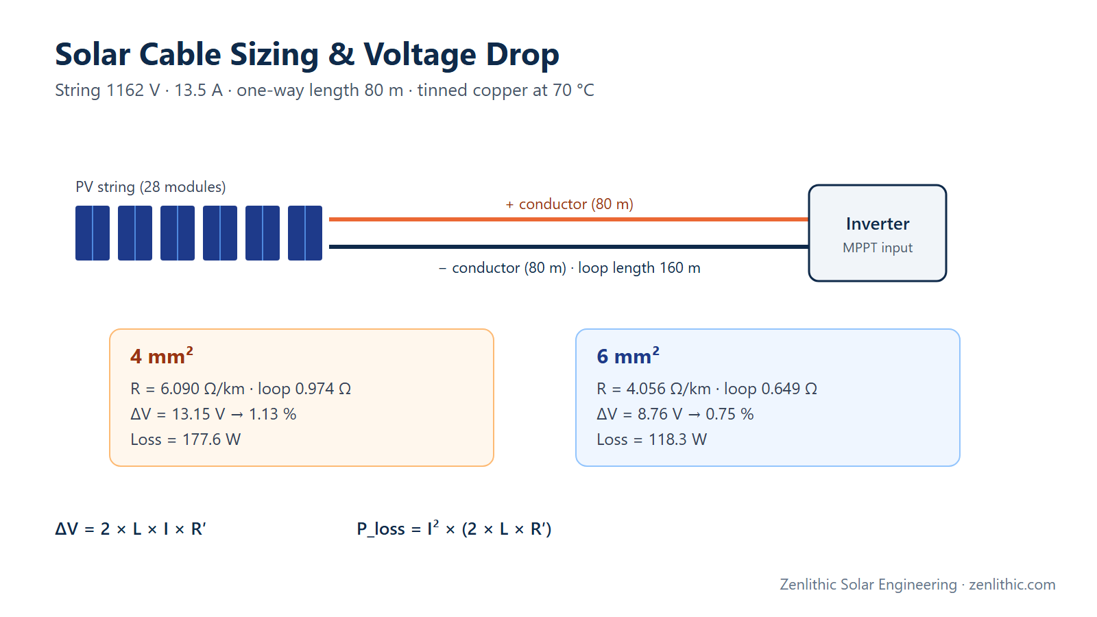
- It sets string cable lengths and routing in the DC layout (see solar cable sizing and voltage drop).
- It is entered in PVsyst under System → Array design; PVsyst recalculates the same voltage checks using its own temperature model.
Design Considerations
- Use the lowest expected ambient temperature from long-term data (record low), not the design average. For very cold sites this single input usually decides N.
- Use the lower of the inverter maximum DC voltage and the module maximum system voltage.
- Check against the full-power MPPT range, not just the operating MPPT range: many inverters track down to a low voltage but cannot deliver rated power there.
- Account for DC cable voltage drop when checking the low-voltage limit at the inverter terminals.
- Bifacial modules: rear irradiance raises current far more than voltage — apply the extra current allowance to MPPT and cable checks.
- Module degradation slightly reduces Vmp over time; for long strings near the lower MPPT limit, check end-of-life voltage too.
- Mixed orientations must not share an MPPT unless their strings have identical module counts and similar irradiance profiles.
Common Mistakes
- Using Voc at STC (1386 V for 28 modules) instead of cold-corrected Voc (1465.8 V) — this is how strings end up over-voltage in winter.
- Using the Pmax coefficient as if it were the Voc coefficient — γ is larger in magnitude and gives a different answer.
- Using the average winter minimum instead of the record low.
- Checking only the maximum voltage and forgetting the hot-day Vmp against the full-power MPPT window.
- Forgetting the inverter's input-current limit, then adding a third string to an MPPT and clipping current.
- Mixing strings of different lengths on the same MPPT.
Key Notes
- Series connection adds voltage; parallel connection adds current.
- Cold weather is the maximum-voltage case; hot weather is the minimum-voltage case.
- Maximum voltage is a safety limit; minimum voltage is an energy limit.
- The βVmp ≈ γ − αIsc relation is an approximation — prefer datasheet values.
- Margins beyond the calculated limits are a project policy, not a standard requirement.
Engineer's Checklist
- Module and inverter datasheets are the exact models to be procured
- Record-low ambient temperature taken from long-term site data
- Highest cell temperature estimated (ambient max + irradiance rise)
- Voc corrected with βVoc (not γPmax)
- N ≤ floor(min(V_inv,max, V_module,max) / Voc,cold)
- Hot-day string Vmp ≥ full-power MPPT minimum (after DC voltage drop)
- Cold-day string Vmp ≤ full-power MPPT maximum
- Operating current per MPPT ≤ inverter limit
- 1.25 × Isc (plus bifacial allowance) per MPPT ≤ inverter short-circuit limit
- Same string length and orientation on each MPPT
- PVsyst model shows no voltage/current warnings
- Configuration recorded in DBR and string layout drawing
FAQ
How do I calculate the maximum number of solar modules in a string?
Correct the module's Voc to the lowest expected ambient temperature using the Voc temperature coefficient, then divide the lower of the inverter maximum DC voltage and the module maximum system voltage by that corrected Voc and round down.
Why is the minimum temperature used for the maximum string voltage?
PV voltage rises as cell temperature falls. The highest voltage appears at sunrise on the coldest day, when the modules are at about ambient temperature and the string is at open circuit.
Which temperature coefficient should I use for Vmp?
Use the Vmp coefficient if the datasheet gives it. If not, βVmp ≈ γPmax − αIsc is a common approximation. Do not use the Voc coefficient for Vmp — it underestimates the voltage drop at high temperature.
Why check the full-power MPPT range and not just the MPPT range?
Many inverters can track the maximum power point over a wide voltage range but can only deliver rated power over a narrower full-power range. Below it, output is limited.
How many strings can I connect to one MPPT?
Divide the inverter's maximum input current per MPPT by the string Imp and round down, then confirm that the number of strings × 1.25 × Isc (plus any bifacial allowance) is within the inverter's maximum short-circuit current per MPPT.
Does string length change for bifacial modules?
Voltage limits are almost unchanged, because rear irradiance mainly increases current. The current checks (strings per MPPT, cable and fuse sizing) must include the bifacial gain.
What happens if a string exceeds the maximum DC voltage?
The inverter may trip or be damaged, and module insulation ratings are exceeded. It is a safety non-conformity, not merely an energy loss.
Conclusion
String sizing is a bounded problem: the cold-weather Voc sets the maximum string length, and the hot-weather Vmp sets the minimum. In the worked example both 26 and 28 modules pass, but 28 modules gives better economics with a 2.3 % voltage margin, which is acceptable only if the record-low temperature data is trustworthy. Next, use the string configuration to set strings per inverter and the DC/AC ratio.
Related reading: DC/AC ratio and inverter sizing · Solar cable sizing and voltage drop · PR, CUF and generation calculation
Need professional solar PV design, PVsyst simulation, AutoCAD drawings or electrical design support? Zenlithic provides solar design consultancy and engineering support for rooftop, C&I and utility-scale projects — including string design, DC/AC layouts, SLDs and DBR documentation. Explore Zenlithic Solar or contact our engineering team.