The single line diagram (SLD) is the most important electrical drawing of a solar plant. It is submitted for approvals, used by the EPC to procure equipment, checked by the utility before connection and used by O&M for switching and fault-finding. A good SLD lets an engineer understand the whole power path — and every rating and protection device on it — from one sheet.
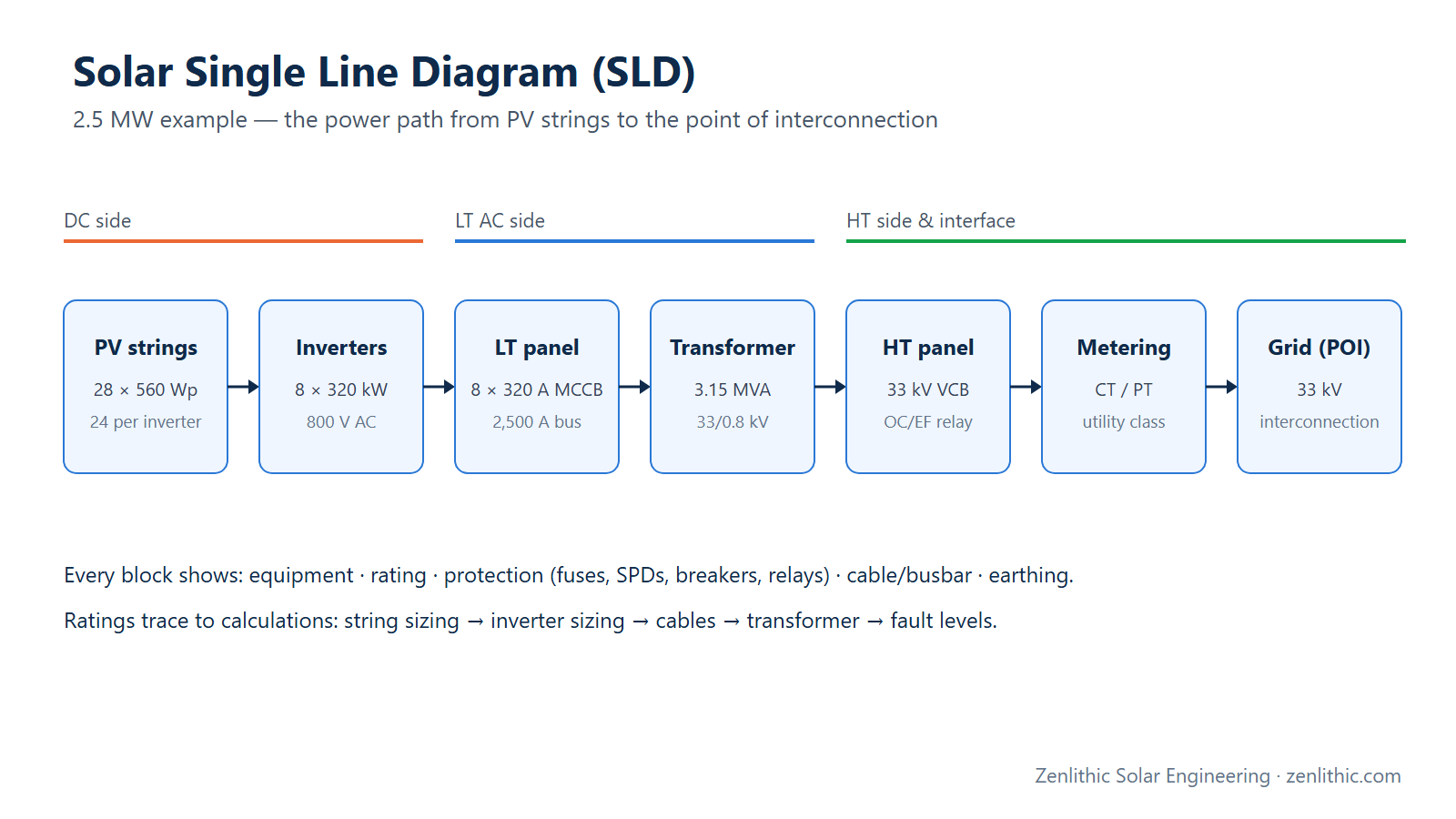
Quick answer: a solar SLD shows the power path on one line per circuit, left to right or top to bottom: PV strings → string combiner boxes or string inverters → inverters → LT panel → step-up transformer → HT switchgear → metering → point of interconnection, with each device's rating, cable sizes, protection (fuses, SPDs, breakers, relays), CT/PT ratios, metering class and earthing. For a 2.5 MW plant with eight 320 kW inverters, that means 320 A outgoing MCCBs, a 2,500 A LT bus, a 3.15 MVA 33/0.8 kV transformer and a 33 kV breaker with overcurrent and earth-fault protection.
Introduction
Beginner understanding: Real plants have three-phase cables with several conductors, but drawing every wire would be unreadable. A single line diagram draws each circuit as one line and each device (inverter, breaker, transformer) as a standard symbol, so you can follow how power flows from the panels to the grid.
Engineering understanding: The SLD is the authoritative record of the plant's electrical topology and ratings: equipment ratings and quantities, conductor sizes, protective devices and their ratings/settings, instrument transformers, metering, earthing and interfaces with the grid. It must be consistent with the DBR, BOQ, cable schedule, protection study and PVsyst model, and it uses standard graphical symbols (IEC 60617).
What is it?
| SLD section | Typical content |
|---|---|
| DC | Strings (modules × strings), string/array cables, combiner boxes (fuses, DC SPD, isolator) or direct string-inverter inputs |
| Inverter | Quantity, kW/kVA, AC voltage, MPPTs |
| LT (LV AC) | Inverter outgoing breakers, AC SPD, LT panel busbar, incomer ACB, LT cables |
| Transformer | kVA, voltage ratio, %Z, vector group, cooling, neutral earthing |
| HT | RMU/VCB panels, protection relays, CT/PT, HT cables, auxiliary transformer |
| Metering & interface | Main/check meters, CT/PT class and ratio, isolator, point of interconnection |
| Earthing & notes | Earthing references, SPD types, abbreviations, reference drawings |
Why is it important?
- Required for statutory and utility approvals (for example electrical inspectorate/CEIG and DISCOM approvals in India).
- Drives procurement: every rating in the BOQ should trace to the SLD.
- Basis for protection coordination and short-circuit studies.
- Essential for safe switching and O&M.
When is it used?
Concept stage (block SLD), detailed engineering (full SLD with ratings), approvals, procurement, commissioning (IEC 62446-1 documentation) and throughout operation (as-built SLD).
Where is it used?
Every grid-connected plant — rooftop (often a simple LT SLD with net/gross meter), C&I (LT or 11 kV connection) and utility-scale (DC, LT, multiple transformer blocks, 33 kV collection, pooling substation, EHV evacuation).
How does it work?
The SLD follows the power flow and, at each stage, answers four questions: what equipment, what rating, how is it protected, and how is it connected (cable/busbar). Ratings come from the design calculations: string sizing, strings per MPPT, inverter sizing, cable sizing and transformer sizing.
Required Input Data
- Module and string configuration; inverter datasheet (kW, kVA, max AC current, AC voltage).
- Cable schedule (sizes, lengths, types).
- Transformer data (kVA, ratio, %Z, vector group).
- Grid voltage, fault level at the interconnection and utility protection/metering requirements.
- Earthing and SPD design.
Step-by-Step Design Process
- Draw the block structure: how many inverters per LT panel, how many LT panels per transformer, how the HT side connects.
- DC section: strings per inverter/MPPT, string cable size, DC SPD and isolator (or combiner fuses where needed).
- Inverters: quantity, kW/kVA, AC voltage.
- LT panel: outgoing breakers per inverter, busbar rating, incomer ACB, AC SPD, metering/monitoring CTs.
- Transformer: kVA, ratio, %Z, vector group, cooling, neutral earthing.
- HT switchgear: breaker/RMU, protection relays and functions, CTs/PTs, HT cable.
- Metering and interface: meter class, CT/PT ratios and accuracy, isolation point, point of interconnection.
- Notes and legend: symbols, abbreviations, SPD types, earthing references, standards.
- Cross-check every rating against the DBR, BOQ, cable schedule and PVsyst model.
Formula
Breaker rating (inverter outgoing) ≥ 1.25 × inverter max continuous AC current   (common practice; check the applicable code)
LT busbar/incomer ≥ Σ inverter max AC current and ≥ transformer LV rated current
Transformer LV current I = S / (√3 × V_LV) ;  HV current I = S / (√3 × V_HV)
LV fault level ≈ I_LV / z
Numerical Example
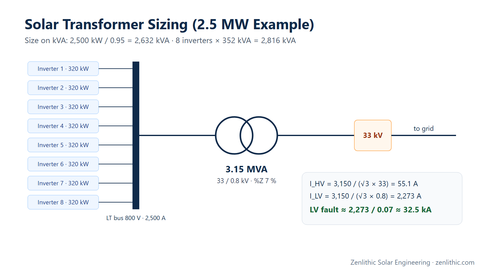
The 2.5 MW plant from our transformer sizing example: eight 320 kW / 352 kVA string inverters at 800 V (maximum continuous AC current 254 A each — assumed datasheet value), one 3.15 MVA 33/0.8 kV transformer (%Z = 7 %), connecting at 33 kV.
Engineering Calculation
LT section
Inverter outgoing breaker ≥ 1.25 × 254 A = 317.5 A → 320 A MCCB (8 nos.)
Σ inverter current = 8 × 254 A = 2,032 A
Transformer LV rated current = 3,150 / (√3 × 0.8) = 2,273 A
LT busbar and incomer ACB ≥ 2,273 A → 2,500 A
LV fault level ≈ 2,273 / 0.07 ≈ 32.5 kA → LT panel short-time rating ≥ this (plus inverter contribution per OEM)
HT section
Transformer HV current = 3,150 / (√3 × 33) = 55.1 A
HT breaker (VCB/RMU): rated current well above 55 A (standard ratings start in the hundreds of amps);
                      short-circuit rating ≥ the utility's fault level at 33 kV
Protection CT: ratio selected above 55.1 A (e.g. 75/1 or 100/1, per relay and utility requirements)
SLD equipment summary
| Section | Equipment | Rating (example) |
|---|---|---|
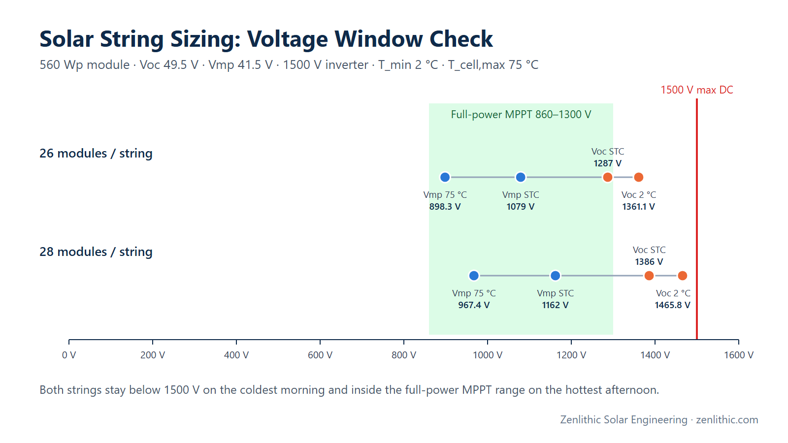
| DC | Strings | 28 modules × 560 Wp, 2 strings per MPPT, 24 strings per inverter |
| DC | String cable | 1C × 6 mm² Cu (EN 50618), DC SPD Type 2 at inverter |
| Inverter | String inverters | 8 × 320 kW / 352 kVA, 800 V |
| LT | Outgoing MCCBs | 8 × 320 A |
| LT | Busbar / incomer ACB | 2,500 A, AC SPD Type 2 |
| Transformer | Inverter-duty | 3.15 MVA, 33/0.8 kV, %Z 7 %, ONAN |
| HT | VCB / RMU panel | 33 kV with overcurrent and earth-fault protection |
| Metering | Main and check meters | CT/PT and meter class per utility metering regulations |
| Interface | Point of interconnection | 33 kV utility substation/line |
Practical Solar Application
- The SLD is drawn in AutoCAD with a consistent layer scheme and standard symbols, and issued with a revision table — every design change must update it.
- The metering section must follow the utility's and the applicable metering regulations (in India, the CEA metering regulations and DISCOM requirements), including meter and CT/PT accuracy classes.
- Protection settings (relay functions such as overcurrent, earth fault, and any utility-required interface protection) come from the protection study and utility approval.
- As-built SLDs are part of the commissioning handover documentation (IEC 62446-1).
Design Considerations
- Consistency: DC kWp, inverter count, transformer rating and export capacity must match the DBR, BOQ and PVsyst.
- Earthing: show system earthing (TN/IT arrangement on LV as required by the inverter OEM), transformer neutral treatment and equipment earthing references (see IS 3043 / IEC 62305 for earthing and lightning protection).
- SPDs: DC and AC surge protection at the right locations and types (IEC 61643 series).
- Auxiliary supply: auxiliary transformer and UPS for SCADA/protection.
- Isolation points: visible isolation for safe maintenance at each voltage level.
- Standards: modules (IEC 61215/61730), inverters (IEC 62109; IS 16221 in India), cables (EN 50618/IEC 62930 DC, IS 7098 XLPE AC), grid connectivity (CEA regulations in India). Confirm editions required by the tender or DISCOM.
Common Mistakes
- Ratings on the SLD that don't match the BOQ or DBR.
- Breakers sized on inverter kW instead of maximum AC current.
- LT panel short-circuit rating below the transformer LV fault level.
- Missing SPDs, earthing or isolation points.
- Metering CT/PT classes that don't meet utility requirements.
- No revision control — the drawing in the field differs from the approved one.
Key Notes
- Power path: strings → inverters → LT panel → transformer → HT switchgear → metering → POI.
- Every device needs rating, protection and connection shown.
- Breakers ≥ 1.25 × inverter max AC current (common practice; confirm with the applicable code).
- LT panel short-time rating ≥ LV fault level.
- The SLD must match DBR, BOQ, cable schedule and PVsyst.
Engineer's Checklist
- Block structure and quantities correct
- DC: strings, cables, SPD, isolators/fuses shown
- Inverters: kW, kVA, voltage, quantity
- LT: breakers, busbar, incomer, SPD, CTs rated and shown
- Transformer: kVA, ratio, %Z, vector group, earthing
- HT: breaker/RMU, relays, CT/PT ratios
- Metering per utility regulations
- Fault levels checked against switchgear ratings
- Legend, notes, standards and revision table present
- Consistent with DBR, BOQ, cable schedule, PVsyst
FAQ
What is an SLD in a solar plant?
A single line diagram: a simplified electrical drawing showing each circuit as one line, with the equipment, ratings, protection and metering from the PV strings to the grid connection.
What must a solar SLD include?
Strings, combiner boxes or string inverters, inverters, LT panel, transformer, HT switchgear, metering and the point of interconnection, plus ratings, cable sizes, protection devices, CT/PT data and earthing.
How do I size the inverter breaker on the SLD?
Use the inverter's maximum continuous AC current from the datasheet; common practice is at least 1.25 times that value, rounded up to a standard rating (for example 1.25 × 254 A → 320 A). Confirm with the applicable code.
Which standard defines SLD symbols?
IEC 60617 defines graphical symbols for electrical diagrams; many utilities also have their own drawing requirements.
Is the SLD needed for rooftop solar?
Yes — even small rooftop systems submit an SLD for net-metering or inspection approval, usually a simple LT diagram with the inverter, protection and meter.
Conclusion
A solar SLD tells the complete electrical story of a plant on one sheet. For the 2.5 MW example: eight 320 kW inverters on 320 A MCCBs, a 2,500 A LT bus rated above the ≈ 32.5 kA LV fault level, a 3.15 MVA 33/0.8 kV transformer and a 33 kV breaker with protection and utility-grade metering. Every one of those ratings traces back to a calculation.
Related reading: Solar transformer sizing · Solar cable sizing and voltage drop · Strings per MPPT
Need professional solar PV design, PVsyst simulation, AutoCAD drawings or electrical design support? Zenlithic provides solar design consultancy and engineering support for rooftop, C&I and utility-scale projects — SLD drafting in AutoCAD, protection and metering schemes, HT/LT design and approval documentation. Explore Zenlithic Solar or contact our engineering team.